Einleitung auf Deutsch

Stationäre Spektroradiometer-Systeme können durch einen Besuch des QASUME Spektroradiometers kalibriert werden. Der Besuch dauert in der Regel fünf Tage, wobei zwei Tage für die Reise- und Aufbauzeit und drei Tage für den Vergleich zwischen dem Instrument des Gastgebers und dem Referenzinstrument benötigt werden. Nach einem QASUME Audit wird ein detaillierter Bericht des Vergleichs- und eines Kalibrierzertifikats (siehe Zertifikat C1 und Bericht R1 und Bericht R2) ausgegeben. Es wird empfohlen, dass der Besuch jährlich wiederholt wird, um die langfristige Stabilität des Systems zu gewährleisten.

QASUME Site Audits

Stationary spectroradiometer-systems can be calibrated by a visit of the QASUME spectroradiometer. The visit usually lasts 5 days with two days needed for travel and setup time and 3 days for intercomparison between the host and the reference instrument. After a QASUME audit, a detailed report of the intercomparison and a calibration certificate (see certificate C1 and report R1 and report R2) are issued. It is recommended that a visit is repeated annually to ensure the long term stability of the system.

Irradiance Standard Calibrations

Any type of reference irradiance standard can be calibrated at the WCC-UV relative to the WCC-UV irradiance scale traceable to the PTB. The usual procedure is the delivery of the owners standard lamp to PMOD/WRC, where it is then calibrated. For the return of the lamp special care is needed. Personal delivery is recommended. Examples of calibration certificates can be downloaded here (certificate C2 and certificate C3).

UV Broadband and Filter Radiometer Calibration

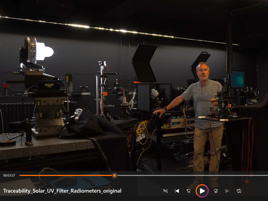
The calibration procedures initially consists of measuring the Spectral Response Function (SRF) and the Angular Reponse Function (ARF). These laboratory and outdoor measurement procedures are described in a new video by Gregor Hülsen, entitled “The traceability of solar UV radiometers”.

Please click on the video to watch →
Measurement of the Spectral Response Function (SRF)

Radiation measurements with broadband filter radiometers fundamentally depend on the relationship between the measured spectral radiation spectrum and the spectral responsivity of the radiometer. Different spectral radiation distributions will produce results which not only depend on the amount of radiation received by the detector, but also on their relative spectral shape.

Furthermore, the detector spectral response will usually not be identical to the nominal spectral sensitivity for which the radiometer was designed, for example the erythemal action spectrum. This implies that the calibration of such a radiometer will depend on the spectral source function and the spectral filter response. Suitable correction functions will therefore be required to convert from the detector weighted radiation to that of the desired weighting function.

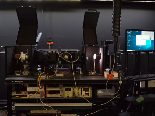
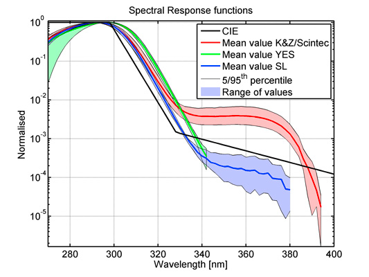
Measurements of the spectral response function (Figure 1) for the three major type of radiometers can be seen in Figure 2. The SRF characterisation results in a calibration certificate (certificate C4).

Figure 1. The set-up to measure the Spectral Response Function (SRF).

Figure 2. Examples of spectral response functions. Displayed are the mean and standard deviation of the SRFs of five Kipp & Zonen and two Scintec, nine YES UVB-1 and 10 Solar Light SL501A radiometers.

Measurement of the Angular Response Function (ARF)

In a similar context, as described for the SRF measurements, irradiance measurements require the detector to weight incoming radiation with the cosine of the incoming angle relative to normal incidence. Deviations from this angular response will usually result in diurnal variations and may also depend on the atmospheric state. This is especially true for measurements in the UV wavelength region where the relative proportions of the direct un-scattered solar radiation to the diffuse radiation changes substantially during the day and depends significantly on the solar zenith angle.

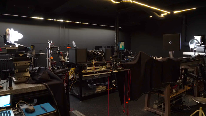
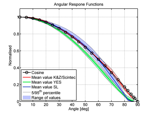
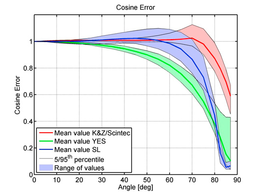
Measurements of the actual angular response function (Figure 3) and their deviation from the ideal cosine function for the three major types of radiometers can be seen in Figures 4 and 5. The ARF characterisation results in a calibration certificate showing the angular response for the four planes of the radiometer filter and the resulting cosine error (see certificate C5).

Figure 3. The set-up to measure the Angular Response Function (ARF) can be seen in the foreground. A UV radiometer is being illuminated (on the left) by a light source (on the right).

Figure 4. The mean and standard deviation of the ARFs of sets of different radiometer types (same as in Figure 2).

Figure 5. The cosine error of various instruments.

Absolute Calibration

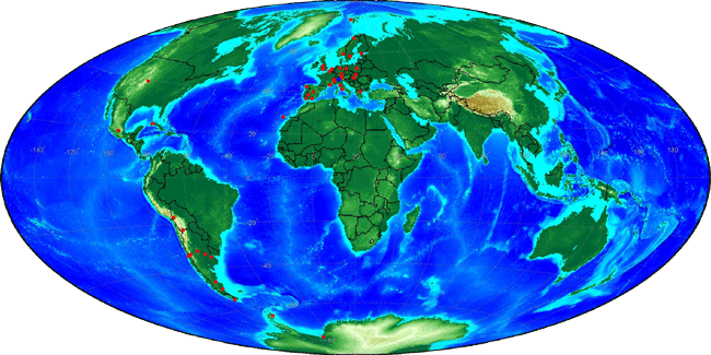
The absolute calibration factor of the instrument is obtained during an outdoor calibration. The signal of the radiometer is recorded for several days and compared to the reference spectroradiometer.The resulting certificate will provide all the necessary calibration factors to convert from the raw signal to weighted irradiance (see certificate C6). These factors are first, the absolute calibration factor; second, a function to convert from the irradiance weighted with the detectors’ specific function to the desired weighting function; third, a suitable cosine correction function. Figure 6 shows a map of all broadband and multichannel radiometer locations which have been calibrated at PMOD/WRC, or where the calibration of the instrument is directly traceable to the WCC-UV.

Figure 6. Locations of all broadband radiometers calibrated at PMOD/WRC or traceable to the WCC-UV.

Spectroradiometer Calibration

Spectroradiometers with either a global or direct input optic can be calibrated at the irradiance standard calibration setup. As for those standards, the calibration is traceable to the PTB and thus to the SI units W.m-2.nm-1. Both, scanning devices and array spectroradiometers can be calibrated for irradiance and radiance.

For further information please contact: Dr. Julian Gröbner, Dr. Gregor Hülsen, Dr. Luca Egli